Since the project is a database, the content automatically related to the model itself.
Preparing the Layout - creating sheets
You can set up your plot layout via the Documentation > Prepare plot layout command.
In the dialog, you have the following options (2021 version):

- Paper size setting: to prepare printing, you need to define the plot layout size. This format might be different from the actual printing format. The user can also define customized sizes. The default format is determined by that actual paper size which is used by the current printer, so it is recommended to use that.
- Number of sheets in column rows: you can place multiple sheets with or without stamp in one step.
- Plot layout name (A-): View name in Project Navigator.
- Orientation: the Orientation defines the position of the paper. Portrait or Landscape can be selected from Paper Size.
- Non-printable Margin: the dialog displays the margin values that belong to the current printer driver. They are the absolute minimum; you should not enter values less than these because it might happen that some part of the drawing will be out of the paper printable area.
- Plot stamp placement: select a plot stamp template from the list, or click Select New Item (Blue Cross) button to select other plot stamps.
Note: How to calculate the printable area? You can get the dimensions of the printable area if you take away the least margin size required by the printer from the size of particular sheet of paper The dimensions of the printable area can be calculated as follows: Printable area length = paper length - (top + bottom margins Printable area width = paper width - (left + right margins).
When you press OK, the ARCHLine.XP will create a new Print Page window and if you activated in the dialog the Plot Stamp Placement option, the program will automatically place the selected plot stamp on the sheet.

Inserting Views on Sheet
Click and drag a view by its name on the sheet from the Project Navigator. Releasing the mouse button above the print layout window, you can specify the scale of the view in the appearing menu.

Placing cropped area
If you just want to insert a cropped area, e.g. from the floor plan do the following:
- Activate the view from you want to copy the content (in this example, this is the floor plan).
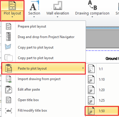
- Choose Ribbon bar / Documentation / Plot layout / Copy part to plot layout command.
- Select the part you want to copy (by drawing a rectangle or closed polygonal shape around the content).
- Specify the reference point with which you want to grab the cropped area.

- Activate the plot layout.
- Select Paste to plot layout command from the Ribbon bar / Documentation / Plot layout group and specify the scale to which you want to place the cropped area on the sheet.

- Place the cropped area on sheet.
Note: After loading and placing the view or a cropped area on the sheet you can freely add dimensions, texts, symbols, e.g. North Symbol, and images. From the Project Navigator, you can place the saved photorealistic images of the 3D model too.
The Plot Layout is a dynamic drawing, so a change to the original drawing can be displayed on the layout. To do this, click with right button on the relevant and click on Refresh this command.
Inserting images
Go to Ribbon bar > Drafting > Raster Image > Place
Printing the Sheet
Make sure the Plot Layout view is the active view.
Location: Documentation > Print
Printing in a print queue
You can place all drawing sheets in one step in the Print Queue: Print queue - Improved performance
Kommentare
0 Kommentare
Zu diesem Beitrag können keine Kommentare hinterlassen werden.